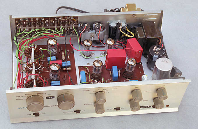
The modified PAS preamplifier with purist line stage, (re)built in 1996.
SPICE and the art of preamplifier design
Part 2: New preamplifier designs
by Norman L. Koren
Updated August 20, 2001
In part 1 we discussed how important aspects of preamplifier design such as susceptibility to RF interference and negative feedback can be studied using SPICE. We described the Dynaco PAS preamplfier-- its circuit and performance. In this part we present some modifications to the PAS, designed with the help of SPICE, that solve the problems in the original design, and we go beyond mere modifications to present some remarkable high-end designs.
With the help of SPICE, we have been able to design a feedback phono preamplifier with flawless performance (above). Except for a few small changes, the circuit topology is similar to the '94 mod. We now use dc-coupling in the negative feedback circuit. Since there is little feedback at low frequencies, this makes less difference than it does for the line amplifier, but eliminating an unnecessary capacitor never hurts. We have eliminated the positive feedback resistor (RPFB in Fig. 1) between the gain stage cathodes. We have added resistor RPL at the output to prevent switching pops that can result from charging of output capacitor C5C.
Most importantly, we have added 33 pF capacitor C1M between the grid (node 1G) and plate (node 1P) of input stage TU1. A capacitor connected between a grid and plate is called a Miller capacitor after the Miller effect: Its capacitance must be multiplied by the closed-loop gain of the tube to calculate the correct RC time constant. This capacitor stabilizes the feedback loop (very important because of the extremely high loop gain at high frequencies), reduces sensitivity to RF interference, and continues the RIAA rolloff at very high frequencies. Its value is not critical: 22 to 47 pF is OK. Before it was added, certain Chinese 12AX7's (which may have high cathode-to-grid capacitance) appeared to oscillate, as evidenced by a large pop not audible with other tubes when the PAS was switched to PHONO. Adding C1M eliminated the pop, and the Chinese tubes now sound beautiful. Transient response problems in feedback phono preamplifiers can be completely eliminated by the addition of a Miller capacitor. C1M also gave the PAS a stronger subjective sense of silence in quiet passages: something that can be felt rather than measured.
The RIAA network has been recalculated to improve frequency response accuracy and to increase feedback at low frequencies so that errors due to differences between tubes are minimized. Since the original design has more then enough gain for modern moving magnet cartridges, we are able to increase feedback by reducing circuit gain. The redesign started by reducing RIA2 from 4.7MEG to 2.2MEG. Other component values (RIA2, CIA1, CIA2) were determined by trial-and-error. Frequency response (below) is nearly ruler-flat from 20Hz to 100kHz. Unless you are using the SPECIAL input for a microphone (in which case you're on your own) I recommend removing the wires that connect terminals 2, 3, 8, and 9 of the phono preamp board to the selector switch and removing the 750pF capacitors from the selector switch. All they do is pick up noise. Place CIA1 on the board at the original locations of the 68pF capacitors.
We present four line amplifiers. The first two are suitable as PAS modification. They aren't too complex and they don't draw too much plate current for the wimpy PAS power supply. You should consider the second two if you plan to build from scratch.
In the original article we presented three versions of the line amplifier with tone controls. Version 1 used the old tone control potentiometers, which work pretty well, but were custom-designed and cannot be replaced if they go bad. Components have been recalculated for improved flatness when the controls are centered. Version 2 used widely-available linear pots and has a more restricted tone control range. Both versions 1 and 2 both required that the total load (internal + external) be set to a precise value, normally 50k, with 20k or 10k available as options. This means that you may need to replace an internal load resistor when you change power amplifiers. Version 3 has the huge advantage that it works with any reasonable load impedance. Because versions 1 and 2 are of little practical interest, I've dropped them from the article.
The addition of cathode follower TU6 increases the gain of second stage TU4 by 12 dB over the original overloaded PAS. If we did nothing to reduce the gain of TU4, the signal at the plate 3P of input stage TU3 would be attenuated by 13 dB, which worsen the sonic degradation due to RF interference coupled from the output cables. To prevent this problem, we have reduced the gain of second stage TU4 by means of local feedback, which is implemented by connecting grid resistor R4G to junction 4B between R4C and R4B. Local feedback is extremely stable and delivers all the usual benefits: reduced distortion and output impedance, improved frequency response, etc. It also improves stability by decreasing the amount of global negative feedback. Distortion is an astonishingly low 0.0027% for a 1V (0-Peak) input signal and a 4.40V (0-Peak) output signal, far below that of the original PAS.
In the original PAS, the feedback loop is stabilized by 33 pF capacitor CLFB in shunt with feedback resistor RLFB. In the present modification, we eliminate CLFB, replacing it with Miller capacitor C3M connected between input stage grid 3G and plate 3P. We also add C3C connected between input stage cathode 3C and ground to shunt RF interference from the output cable. R3GS and C3M provides the dominant pole that controls open-loop rolloff and assures stability. The validity of this technique was confirmed by a recent article in the Journal of the Audio Engineering Society, which used a highly mathematical analysis to determine that feedback with Miller compensation is a superior approach to error-correcting amplifier design.12 The first gain stage is the appropriate location of this pole because it suppresses out-of-band interference in succeeding stages. This approach helps stabilize the preamplifier when capacitance is added in parallel with the load, which is unavoidable since cables have 20 to 40pF per foot.
An important feature not in the original 1997 article is the addition of a 150 ohm series resistor, ROUT, to the output. This resistor, which is widely used in solid state designs13 stabilizes the response under extremely large capacitive loads. In a non-feedback amplifier, capacitance in shunt with the load reduces high frequency response. In a feedback amplifier, shunt capacitance destabilizes the feedback loop, leading to a high frequency peak in the response. The addition of this capacitor increases the effective output impedance, resulting in a balance between the two effects. Frequency response is nearly unaffected by shunt capacitance up to 1200 pF. ROUT effectively isolates the line amplifier from the load.
An additional advantage of the new design is illustrated in the figure below, which shows the signal at input stage plate 3P when input signal VIN is applied to the output terminal, LINE_OUT. The traces represent the following conditions:
The only grid-stop resistor in the line amplifier is R3GS on input stage TU3. All other grids are connected directly to the preceding stage. We have found that a single grid-stop resistor on the input stage of a feedback loop is very useful as a part of the dominant pole (RC network) that stabilizes the loop and as a means of reducing RF feedthrough from the input. Feedback theory teaches that if one grid-stop resistor is a good thing, two are pretty bad, and three almost guarantee oscillation.
Using Miller capacitance to stabilize the feedback loop increases the sensitivity of frequency response and phase margin to the setting of volume control RVOL (more precisely, the equivalent Thevenin resistance between the input stage grid 3G and ground). R3GS is set to a relatively high value of 27k to reduce this sensitivity without incurring an excessive noise penalty. The -1dB frequency is lowest with RVOL set to half (-6dB): 50 kHz (Figs. 5,6). With RVOL set for very low or maximum volume, the -1 dB frequency increases to around 90kHz. Phase margin is somewhat reduced, but still excellent.
Output response is down 1 dB at 8 Hz. My instruments can't measure extreme low frequency rolloff, but high frequency rolloff measurements are surprisingly close considering that stray capacitance hasn't been modeled. A small 0.04 Hz peak is observed on first gain stage plate 3P, but its gain is less than the mid-frequency gain. The original PAS has a 0.4 Hz peak 40 dB above the mid-frequency gain. Output impedance ZOUT is measured by connecting input voltage VIN to LINE_OUT (similar to the RF sensitivity measurement above), plotting V(LINE_OUT)/I(VIN) in Probe, and then setting the Y-axis to logarithmic display for clarity. It is below 250 ohms between 500 Hz and 20 kHz, increasing to 650 ohms at 100Hz and 120kHz. Thanks to the stabilizing effect of ROUT, it can drive any practical length of cable. Below about 500 Hz output impedance is dominated by output coupling capacitor COUT, which is a 630V monster in my mod (Fig. 16) because the Wima supplier didn't have capacitors over 1uF rated at 250V. The sound is superb in every respect. (You didn't expect apologies, did you?) As compared to the 1994 mod,5 low frequency rumble and grinding sounds due to the 0.4 Hz peak are gone, bass is tighter, highs are smoother, and silent passages between music seem quieter. Between this and The Emperor's New Amplifier, I've become contented-- ruined an audiophile. I just enjoy the music.
The tone control action is illustrated below. We have used the parametric capability of SPICE to generate these curves. The tone control range is +5.4dB/-5.4dB at 50Hz and +7.3dB/-5.4dB at 10kHz. This relatively limited range assures flat response with the tone controls centered. Output impedance is lower than for previous versions with tone controls because C3G is in the input circuit. With this circuit you never have to worry about your power amplifier's input impedance.
To make more room on the chassis, remove the old filament supply selenium rectifier and 2000 uF filter capacitors and replace them with modern silicon diodes (The low noise fast recovery FR303, available from Mouser, is recommended) and compact electrolytic capacitors mounted close to the rear of the chassis. This makes space available behind the line amplifier PC board for two 9 pin miniature tube sockets for the additional 12AX7s.
Replace the 12X4 rectifier with two 1N4948 fast recovery low noise rectifiers, also available from Mouser. Add extra filter capacitors (150 uF or greater; 400V): one of them above the 12X4 socket and two of them close to the rear of the chassis. Mount a 12.6 V transformer for powering the filament windings (Radio Shack 273-1352 recommended) on the back of the chassis, running the wires inside. The 1 ohm 2W (minimum) resistor in series with the secondary reduces output voltage to the proper level. Install a new 100k dual-ganged audio taper volume control. Mouser part 313-2420-100K does nicely, but a more accurate precision potentiometer would be desirable. I recommend improving the ventilation of the PAS: The solid cover keeps in enough heat to reduce the longevity of some components. I used a chassis punch to make clean holes in the cover above each tube, above the power transformer, and one on each side. Replacing the solid cover with a grill would be very nice if you can find the right material.
The original PC boards were used: Layout is not optimum but it works surprisingly well. The first step was to tear out all components not used in the present design. There were several places where three leads had to be soldered together off the board. This would be unacceptable in a production preamplifier, but OK in an individual project if done with great care. I often use silicone seal to stabilize components, like the giant 3.3uF 600V output coupling capacitors. Note that RLOAD is the power amplifier input impedance: It does not go into the PAS. A new PC board design would be very desirable: I would be happy to collaborate with readers interested in designing boards for practical projects based on this article.
Layout is largely a matter of common sense. Keep wires with high-level output signals well-separated from wires with low-level input signals. Use star grounds where possible to connect signal paths from each stage to the same point. Use parallel capacitors to get within 1% of the specified values for the RIAA network and 5% or better for the tone controls. Coupling capacitors are less critical.
Use metal film resistors where possible, but be sure to the voltage across them well-below their maximum ratings. 1/2 watt resistors suffice in most instances, but it wouldn't hurt to use 1 watt resistors for gain stage plate resistors R1P through R4P and follower cathode resistors R3C and R6C. For example, R6C dissipates E2/R = 1602/120k = 0.21 watts. Some extra margin reduces the effects of heating. Polypropylene or polystyrene capacitors should be employed where possible. I recommend capacitors manufactured by the "Schoopage" or "Schoopen" process (Wima or Solen), in which every capacitor layer contacts the terminating electrode. This maximizes the self-resonant frequency.
The tone controls are entirely out of the signal path when the amplifier is set to flat (wwitch positon 3 closed). This contrasts with the dual-ganged tone control design, where components for for bass and treble boost and cut are always in the circuit, and must balance each other when set to flat, hence must have very tight tolerances. The component tolerances in the new design can be relatively loose; in fact you can easily change them to meet your needs.
I planned to design a power supply with separate MOSFET regulated taps for the two channels, similar to the V+420 circuit configuration in the TENA power supply. Of course I'd use a much heftier power transformer than the PAS.
The modest frequency response steps shown below, ±2 to 3 dB at 50 Hz and 10 kHz, should be sufficient for adjusting the amplifier for different loudspeakers and room acoustics. Don't expect dramatic bass or treble boosts.
Frequency response of line amplifier with 5 position rotary switch
tone controls
I tried a 12AX7 in the first gain stage, but its high plate resistance resulted in poor high frequency response-- it was down 5 to 6 dB at 100 kHz. You need global feedback to get good response out of the 12AX7. The 12AU7 was down only 2.5 dB at 100 kHz. The 68 pF capacitor, C37, boosts high frequency output response so that it is down only 1 dB at 100 kHz. With no global feedback there is no low frequency resonance. The local feedback on each tube stabilizes the gain. Output impedance is low enough that even a 2000 pF shunt capacitor doesn't cause substantial high frequency loss. As with my other designs, the net ac current drawn from V+320 is near zero. This effectively removes the power supply from the signal path. The simplicity of this circuit appeals to me-- it should be much easier to construct than the version above with the rotary switch tone controls. And don't let the simplicity fool you. This is an extreme high end design, lacking only in fluff.
Luis Alvarez of La Coruña, Galicia, Spain has built a version of this preamplifier.
Although SPICE gives us the opportunity to explore a vast array
of circuit topologies, we have stuck with the traditional cascaded gain
stage pair with cathode follower because it's simple, straightforward,
and its audible and measured performance approach perfection with proper
design, accomplished with the aid of SPICE. It can serve as a standard
of comparison when exploring alternate topologies.
The first two circuits work well as PAS modifications, but if you are starting from scratch, the third and fourth are worthy of consideration. Other changes I'd consider are adding self-biased cathode-followers for buffered tape outputs and modifying the phono preamp so more gain could be selected for moving coil cartridges. But the time has come to take a break from preamplifier design. I've done enough.
The next time you read a review of a $5,000 preamplifier in your favorite mass-circulation stereo magazine, you would do well to ponder whether it was designed with tools and techniques as sophisticated as those presented here. And whether it sounds as good.
(The remainder of this section is somewhat out of date. I'll eventually consolidate it with material in Improved vacuum tube models, Part 2.)
Since the technique for linking drawings to models is quite complex, the MicroSim tutorial should be perused. It would be wise to look it over before continuing with this paragraph! To call it from Schematics, click on Help, Contents, and then click on the topic of your choice. The following steps will bring up a good example that can be adapted for tube models. From Schematics, click on File, Edit Library to get into the symbol library editor. Click on File, Open..., eval.slb to open a library file that contains some parts useful as examples. (Be patient: Your screen will still be blank at this point.) Click on Part, Get..., IRF9410 to load the drawing for a P-channel mosfet. (Choose another part if you desire, but this MOSFET is as close as you can get to a tube in this library.) Click on Part, Attributes... to see the statements that define this part. For the IRF9410, they are
template=M^@refdes %d %g %s %s @MODELTemplate links the part to the model library: With appropriate substitutions, for example, IRF9140 for @MODEL, it appears in the netlist. A number on the schematic diagram replaces ? in refdes. To alter an attribute, click on it in the box on the right and edit it in the boxes on the upper left. The attributes of the 12AX7 that link it to its subcircuit in TUBE.LIB are:
refdes=M?
PART=IRF9140
MODEL=IRF9140
template=X^@REFDES %P %G %C @MODELThe 12AX7 SPICE model listed below is excerpted from TUBE.LIB.1 The parameters have been set to match recently-published data11 that appears to be more reliable than data in the old RCA and Sylvania tube manuals.
refdes=TU?
PART=12AX7MODEL=12AX7
.SUBCKT 12AX7 1 2 3 ; P G C; NEW MODELA part may be copied for modification by clicking on Part, Copy, and then entering the appropriate old and new names. To create a new library file (e.g., TUBE.SLB) for your new parts, click on File, New, then File, Save as..., TUBE.SLB (or a full path name of your choice). To insert a part into the new library file, draw it following instructions in the tutorial or modify an existing part (such as the IRF9410), then save it by clicking Part, Save to Library... Either type the library file name or use the usual Windows navigation techniques to locate it. Click on File, Close to return to the Schematics editor. The tutorial contains much more information on how to create and modify symbols for new parts..
+ PARAMS: MU=100 EX=1.4 KG1=1060 KP=600 KVB=300
+ RGI=2000 CCG=2.3P CGP=2.4P CCP=.9P
E1 7 0 VALUE=
+{V(1,3)/KP*LOG(1+EXP(KP*(1/MU+V(2,3)/SQRT(KVB+V(1,3)*V(1,3)))))}
RE1 7 0 1G
G1 1 3 VALUE={(PWR(V(7),EX)+PWRS(V(7),EX))/KG1}
RCP 1 3 1G ; TO AVOID FLOATING NODES IN MU-FOLLOWER
C1 2 3 {CCG} ; CATHODE-GRID
C2 2 1 {CGP} ; GRID=PLATE
C3 1 3 {CCP} ; CATHODE-PLATE
D3 5 3 DX ; FOR GRID CURRENT
R1 2 5 {RGI} ; FOR GRID CURRENT
.MODEL DX D(IS=1N RS=1 CJO=10PF TT=1N)
.ENDS
For MicroSim Schematics to recognize a new symbol library (file pathname\TUBE.SLB that you just created), click on Options, Editor Configuration..., Library Settings. Type the full name of the new symbol library file in the Library Name box, then click Add*, OK, OK. For Schematics to recognize a new model library (file pathname\TUBE.LIB), click on Analysis, Library and Include Files... Type the full name of the new model library file in the File Name box, then click Add Library*, OK.
Parts are entered into MicroSim Schematics drawings by clicking on the little box on the toolbar with the yellow glove and selecting them or by entering a part name such "R", "L", "C", "BUBBLE", etc. in the box to the right of the glove. I recommend using the rubberband option, which can be set by clicking Options, Display Options..., Rubberband. Named nodes (1G, 1P, etc.), created by double-clicking on lines and entering a name, are required for voltages to be examined in Probe. Input files to Schematics have the three character extension .SCH. Clicking Analysis, Create Netlist creates files with extensions .CIR (the control file), .NET (the netlist), and .ALS (an alias file which speeds up analysis) which are used as inputs to Pspice. The .CIR and .NET files contain ASCII text in SPICE format, as described in Paul Tuinenga's excellent text2. Clicking Analysis, Simulate creates the netlist, runs Pspice, and loads Probe to display results. Press the Insert key to select a voltage or current for Probe display. You can use "VDB" or "VP" to display a voltage in dB or its phase in degrees. To display the same variables in repeated runs, click Analysis, Probe Setup..., Restore Last Probe Session. There are many more possibilities for controlling the display.
Fig. A1 illustrates Schematics circuits that can be used to generate characteristic curves for triodes and pentodes. Their netlists are similar to Appendices A1 and A2 of the tube models article1. Each of these circuits requires that you perform a few added steps to generate the characteristic curves. We will use the pentode (Fig. A1b) as an example.
To step the grid voltage, click on Analysis, Setup..., Parametric... Set Swept Var. Type to Voltage Source, Sweep Type to Linear, Name: to VG1, Start Value to 0, End Value: to -75 (or as appropriate), and Increment: to -15 (or as appropriate), then click OK. You may set the plate voltage sweep while the Analysis Setup... box is still open. Click DC Sweep... Set Swept Var. Type to Voltage Source, Sweep Type to Linear, Name: to V_P, Start Value to 0, End Value: to 600 (or as appropriate), and Increment: to 5 (or as appropriate), then click OK. The DC Sweep... and Parametric boxes should contain check marks. Finally, click Close. All voltage sources except VG2NOM are set to DC=0 in the schematic diagram. (Attributes can be viewed and changed by double-clicking on the symbol.) Grid and plate voltages are controlled by the DC Sweep... and Parametric... settings.
VG2NOM is the nominal screen grid voltage. Referring to the tube models article, it is set to 300V in Fig. 3 (pentode mode) and 450V in Fig. 5 (ultra-linear (UL) mode). (It has no meaning in triode mode, where screen grid voltage equals the plate voltage). E2 is an EVAL voltage-controlled voltage source that controls how the screen grid voltage tracks the plate voltage. The value shown in Fig. A2b, V(%IN+, %IN-)*.4+V(101)*.6, is for ultra-linear mode. For pentode mode, set it to V(%IN+, %IN-). For triode mode, set it to V(101). VP and VC are both set to zero: They have been entered as shown so that I(VP) and I(VC) have the correct polarity when plotted by Probe. When you have completed entering the schematic, click Analysis, Simulate. This will create a netlist, run Pspice, and then run Probe to display the results. Error messages can appear at any one of several stages of this process. They are unavoidable when you start out. Don't get frustrated. This is where real learning happens.
Norman Koren Vacuum tube audio page
| Photography page
Feedback and Fidelity
| Improved vacuum tube models for SPICE
simulations
| This page
created December 8, 2003 |
Images and text copyright (C) 2000-2012 by Norman Koren. Norman Koren lives in Boulder, Colorado. Since 2003 most of his time has been devoted to the development of Imatest. He has been involved with photography since 1964. Designing vacuum tube audio amplifiers was his passion between about 1990 to 1998. |  |