SPICE
and the art of preamplifier design
Part
1: Background
by
Norman L. Koren
Updated Sept. 18, 2001
Vacuum tube audio page | Photography
page
Feedback and Fidelity | Improved
vacuum tube models for SPICE simulations
This page is adapted from an article
that originally appeared in Glass
Audio, Vol. 9, No. 2, p. 1 and No. 4, p. 38, 1997. Internet links
have been added. Circuits with current regulator diodes for linearizing
the output have been eliminated because the small reduction in low order
harmonic distortion was offset by a significant increase in noise-- overall
sound quality was degraded. A design with rotary switch tone controls has
been added.
Portions of the material here are repeated
in Feedback and Fidelity, which was
intended for a more popular and less technical publication than
Glass
Audio.
Introduction
A central mystery of high-end audio amplifier design is the poor correlation
between subjective sound quality and conventional measurements (frequency
response, harmonic distortion, etc.). For this reason, many of the choices
involved in amplifier design-- the selection of the overall circuit topology,
the use of negative feedback (NFB) and the often-overlooked tradeoff between
frequency response extension and radio frequency (RF) interference-- have
remained an art. Highly accurate new
vacuum-tube models1 make the SPICE circuit analysis program2-4
into a powerful tool for examining inner details of tube amplifier performance.
With SPICE, you can make unconventional "measurements" on your computer
that would be difficult and costly with hardware instrumentation. By correlating
these new measurements with careful listening, the gap between the art
and science of amplifier design can be narrowed.
In this article we use SPICE to design preamplifiers of exceptional
quality. The platform for experimentation was the venerable Dynaco
PAS.5 So yes, we must confess that this article contains
yet another PAS modification (several, really), but the emphasis will be
on insight into the design rather than on construction details. All observable
flaws of the original PAS have been eliminated, and we have even been able
to replace the unobtainable tone controls (in the line amplifier versions
that use them) with easy-to-find linear potentiometers. The most important
construction details-- the chassis and power supply modifications-- have
been presented previously5 and will only be summarized here.
The simulations in this article were run on the PSpice
evaluation package, which consists of Schematics for entering circuits,
PSpice for simulating them, Probe for viewing the simulation results. LTspice can apparently be used for these models. Appendix
A contains some tips on running Pspice. Duncan
Munro has a list
of SPICE vendors that could contain some hidden treasures. Current
versions of PSpice may enforce the maximum number of components more rigorously
than the version I've been using, 6.3. All schematics in this article
should run on current versions, but I've had circuits rejected by 7.1 that
ran on 6.3.
Design
goals
To create a successful product, a designer must have a set of goals and
a viewpoint on how to reach them. These goals usually involve limitations
in size, cost, and power consumption that must be met with minimal sonic
compromise. Limitations impose a discipline on the design process that
can lead to outstanding results. A "money-is-no-object" approach doesn't
guarantee success.
The essential design goals are low distortion (sspecially high order),
high headroom (the ability to produce a much larger output voltage than
required to saturate power amplifiers), flat frequency response well beyond
the audio range, non-inverting output polarity, and no frequency response
irregularities at any stage of the circuit. I don't seek unlimited frequency
response extension because I've found that RF interference picked up in
the cables can cause serious sonic degradation. The preamplifier must be
able to drive any reasonable load over any reasonable length of cable.
This requires low output impedance and a feedback loop that remains stable
under significant capacitive load.
I use negative feedback because it has great advantages and no drawbacks
when properly implemented in a preamplifier. I design for high input impedance
in each gain stage because it allows the use of small coupling capacitors,
which have high self-resonant frequencies, well above the frequency range
where they can affect the feedback loop. I've taken special pains to minimize
the effects of RF interference
introduced from the cables. I didn't use the highly linear mu-follower
circuit, which operates with the full gain (mu) of the tube (too much gain
in many cases and variable from tube to tube) because the compatible type
of negative feedback reduces input impedance. I minimize the effect of
electrolytic capacitors, which are highly nonlinear at best, in the signal
path by configuring the tubes to draw for zero net ac current (or close
to it) from each power supply tap.
The principal limitation imposed on the design was that it had to be
constructed on a Dynaco PAS chassis using the original power transformer,
whose high voltage winding is specified at a wimpy 10mA. I squeezed a little
extra current out of it by using a separate filament transformer mounted
on the back,5 but I was still limited to six tubes (two in new
sockets mounted in chassis holes behind the line amplifier PC board). The
tubes must be 12AX7s, which perform well at plate currents around 1mA,
lower than other popular tubes used in preamplifiers (12AT7, 12AU7, 6DJ8).
The 12AX7 is ideal for use with negative feedback (local or global) because
of its high amplification factor (mu). A high-mu tube with NFB has much
more precisely controlled gain than a low-mu tube without NFB.
I'm skeptical about the advantages of super-premium parts in well-designed
circuits, although I use good quality parts- polypropylene capacitors,
metal film resistors, etc. I believe that when it comes to designing for
optimum sound quality, the magic is in the circuit.
I'm pleased to report that with the help of SPICE modeling, all the
design goals have been met with no compromises. The only limitation is
that it doesn't have enough gain for low output moving coil cartridges,
but its performance with high output cartridges is so outstanding that
many listeners may not be tempted.
Negative
feedback (NFB)
Much of the material in this and
the next sections is covered in greater detail in Feedback
and Fidelity.
The advantages of negative feedback are well-known: It extends frequency
response, reduces distortion, allows precise control of gain, reduces output
impedance and decreases a circuit's sensitivity to component variations.
Nevertheless, its audible side-effects can be so bothersome that it's fallen
out of favor with many audiophiles. We have identified three side-effects.
The first is that NFB causes clipping to become much more abrupt as
an amplifier is driven into saturation: the greater the feedback the harsher
the clipping. This can result in the generation of really nasty sounding
high order harmonics. For this reason feedback must be applied sparingly
in power amplifiers. Saturation is not an issue in the modified PAS
because of its enormous headroom. It can put out up to 50VRMS into high
impedance loads (over 75k). The 1.27mA dc current drawn by the output cathode
follower allows it to source roughly 0.0012RLOAD V(0-Peak) = 0.00085RLOAD
VRMS into low impedance loads. Even with an extremely low load of
5k (driving two power amplifiers, each with a low 10k impedance: a worst
case for biamplified speakers), the PAS can put out 4.25VRMS: well above
the 1VRMS that can drive most power amplifiers into saturation.
The second side-effect of NFB is that it reduces an amplifier's stability.
Poor stability is expressed as a low phase margin, the amount of additional
phase shift (which could result from capacitance shunting the load) needed
to drive the amplifier into oscillation. An amplifier with poor phase margin
will have a high frequency peak in its frequency response and will ring
in response to transient signals, especially when driving difficult, i.e.,
reactive loads. This ringing can cause sonic degradation. The capacitance
of long output cables (20-40pF per foot) is sufficient to cause ringing
in the unmodified PAS. There are several well-known circuit techniques
for stabilizing feedback loops. The original PAS uses the most common of
them: 33pF capacitor CLFB in shunt with 47kilohm feedback resistor RLFB
(Fig. 1). As we shall see, this "solution" is something of a Trojan Horse!
We shall describe a superior technique that has no discernible ill-effects.
Radio
frequency (RF) interference
The third and least-known side-effect of NFB is that the circuit technique
most often employed to stabilize feedback loops, the capacitor in shunt
with the feedback voltage divider resistor as described above, allows RF
signals picked up by the output cable to be fed back to the amplifier input
virtually without attenuation. We have found that RF interference
causes more significant sonic degradation than such better-known phenomena
as harmonic distortion or frequency response irregularities. Every
circuit modification we have made to reduce an amplifier's susceptibility
RF interference has made it sound smoother, sweeter, more pleasant, and
more generally listenable. This has lead us to believe that "grittiness",
"graininess", "harshness", "listener fatigue", and countless other descriptive
epithets that plague amplifiers with otherwise excellent specifications
are largely due to RF interference.
RF interference is caused by a wide variety of sources: radio,
TV, cellular phones (with digital on the way), microwave ovens, lamp dimmers,
flourescent lights, and digital appliances such as computers and CD players.
(It is particularly difficult to eliminate inside CD players, where it
may be as responsible as jitter for "digititis.") It is virtually
omnipresent in urban, suburban, and all but the most remote rural areas.
It varies from time-to-time and place-to-place, and may be responsible
for many of the discrepancies in published amplifier reviews.
The exact mechanism by which RF interference degrades audio quality
is not well-understood. The most likely cause is intermodulation
distortion. Paul Miller6 described a series of experiments in which
he inserted strong RF signals (swept to 200MHz) modulated with random audio
noise (0-20kHz) into several amplifiers, and measured the resulting audio
noise spectra. He claimed to find a strong correlation between the
measured noise spectra and an amplifier's subjective sound quality.
Although RF interference is occasionally mentioned in audiophile media7,
it tends to get lost among dubious tweaks. There is a very simple
test for determining if an amplifier is overly sensitive to RF interference:
Turn the volume up and listen for a pop when you turn a nearby appliance
on and off. A well-designed amplifier will remain silent.
There are five paths through which RF can enter an amplifier:
(1) direct radiation, (2) power lines, (3) internally generated by digital
circuitry or rectifiers8, (4) the input cable, and (5) the output cable
(potentially the most serious in feedback circuits, and certainly the most
neglected). Direct radiation (1) should have little effect on the
well-enclosed PAS. RFI power line filters (for example, Mouser
part 562-851-03/3) can be quite effective with (2). Internally-generated
noise (3) is minimized by the use of fast recovery rectifiers. We
shall deal with (4) and (5) later in this article, taking full advantage
of SPICE's ability to simplify measurements that would be difficult to
perform in hardware, especially with signal generators and oscilloscopes
that have limited frequency response.
Inverse
RIAA network
A highly accurate inverse RIAA network (upper-left in the schematic below)
has been used to obtain the phono preamplifier frequency response. This
network has poles at 500Hz and 500kHz and zeros at 50Hz and 2122Hz. The
500kHz pole (not a part of the RIAA specification) is required because
the total number of poles must be equal to or greater than the number of
zeros in a realizable passive equalizer. Without it, the network output
would increase by 6dB per octave forever. The output of this network differs
from an ideal inverse RIAA network by -1dB at 250kHz and -3dB at 500kHz.
Although this network is realizable and well-suited for SPICE simulations,
it has considerable insertion loss: -50.58dB at 1kHz and -70.5dB at very
low frequencies. A somewhat more practical inverse RIAA network with less
insertion loss has an upper pole at 100kHz, resulting in a -1dB error at
50kHz. It can be constructed by substituting the following values:
RIV2 = 2.2MEG (unchanged), RIV3 = 182k, CIV1 = 1450pF (560 // 560 // 330pF
suggested, where // denotes components in parallel), CIV2 = 412pF (390
// 22pF suggested), and RIV4 = 5360. RIV1 includes the signal generator
impedance: The values of RIV1 and RIV4 are not critical, but the values
of RIV2, RIV3, CIV1, and CIV2 are quite critical and should be measured
individually on a multimeter. Parallel capacitors and series or parallel
resistors should be used to obtain values within about 1%.
ELAPLACE The Laplace
transform part may be used as a substitute for the inverse network. It
has two advantages: (1) It's an exact implementation of the inverse RIAA
network with no high frequency error. (2) It uses fewer parts-- important
if you run into evaluation PSpice limits. But if you want to build a network
for testing you'll have to use the RC network described above. The illustration
on the right shows the use of ELAPLACE.
Poles T1 and T2
and zero T3 may be entered by double
clicking on the PARAM part and entering
the following data.
| Name |
Value |
| NAME1 |
T1 |
| NAME2 |
T2 |
| NAME3 |
T3 |
| VALUE1 |
3180e-6 |
| VALUE2 |
318e-6 |
| VALUE3 |
75e-6 |
|
|
 |
Interpretation
of figures
All figures except the photographs were created by the PSpice Schematics
or Probe programs. The bias voltage indicators (e.g., 146.17 in Fig. 1)
were created with the VIEWPOINT part. The circles that resemble meters
are current probes created with the IPROBE part. They indicate current
in amperes: 3.275E-03 is 3.274mA. The .PARAM statement required for parametric
tone control runs (Figs. 3, 12) was created with the PARAM part. Tube and
node designations are consistent in all figures. Table 1 describes the
traces used in response curves.
| TRACE |
DESCRIPTION |
| VDB(LINE_IN) |
Phono preamplifier response. |
| VDB(LINE_OUT) |
Total amplifier response (including phono).* |
| VDB(LINE_OUT)-VDB(LINE_IN) |
Line amplifier response.* |
| VDB(3P)-VDB(LINE_IN) |
Response at line amplifier input stage
plate, realtive to input.* |
Table 1. Traces used in the response curves
* indicates volume control set to half (-6 dB: worst high frequency
response)
Original PAS schematic diagram
Original
PAS phono preamplifier
The original PAS phono preamp (shown above) has good frequency response
in the audio band (PHONO STAGE, below) except for a 2dB peak around 25Hz.
It has an open-loop gain of 67.7dB, attained with the help of positive
feedback resistor RPFB = 47k connected between the cathodes of the first
and second gain stages (nodes 1C and 2C). Positive feedback is generally
undesirable because it exacerbates the differences between tubes, i.e.,
open loop gain can vary by more than the tubes themselves. Without RPFB,
the open loop gain drops by 4.4dB to 62.3dB. Since the preamp gain is 61dB
around 25Hz, negative feedback is nearly absent at low frequencies. This
means that the low frequency response is very sensitive to tube variations
and can be different for different versions of the 12AX7 (suffixes A, B,
WB, etc.). Mercifully, the response will become flatter- for a while- as
tubes age and increased plate resistance reduces circuit gain. The poor
low frequency control of the phono preamp is partly responsible for the
PAS's reputation of having flabby bass. The new design completely cures
these problems.
Original PAS frequency response
Original
PAS line amplifier
The original PAS line amplifier) has many flaws not apparent from its specifications
(10-40 kHz ± 0.5 dB; 0.05% distortion at 2V output). Chief among
them is a subsonic resonance around 0.4 Hz, close to the frequency of record
warps.10 This resonance is difficult to measure because
most signal generators don't go low enough and because it isn't very evident
at the preamplifier output (LINE_OUT). It appears in the response curve
as a 40dB peak (relative to 1kHz) at the first gain stage plate (node 3P),
where it can cause envelope modulation and time-varying distortion, both
of which degrade imaging and overall audio quality. It may have contributed
to a grindy sound I heard on LP's. It also contributes to the PAS's reputation
for flabby bass.
The audio signal at the first gain stage plate (node 3P) is about 1dB
below that of the grid (node 3G)-- relatively weak in relation to
RF interference from the cables introduced through the feedback loop (CLFB).
This could cause sonic degradation. The signal in the first stage is attenuated
because the line amplifier's closed loop gain, which is controlled by voltage
divider RLFB, R3C, is less than the gain of the second stage (TU4). We
correct this problem in the modified PAS by reducing the gain of the second
stage with local feedback.
The output stage (TU4) is severely overloaded. Its plate resistance
is around 60k, but its total load is only 20k (47k (feedback loop) // 100k
(plate R) // 50k (internal + external load: 510k // 62k // 470k = 50k))
This reduces gain by about 12dB and significantly increases distortion.
Negative feedback keeps the harmonic distortion figure within specification,
but residual intermodulation (IM) distortion may persist. Stressing a tube
in this way may degrade sound quality more than the distortion statistics
indicate.
In Pspice, distortion is measured by inserting signal VIN at LINE_IN.
Double-click on VIN, and set the TRAN attribute to TRAN=SIN(0 1 1K) for
a 1V(0-Peak) 1kHz sine wave signal for the transient analysis. Click
on Analysis, Setup...,
Transient...
Set Print Step to 0.1mS (unimportant), Final Time to 2mS, No Print Delay
to 0, and Step Ceiling to .01mS. Check Enable Fourier, then set Center
Frequency to 1k, Number of harmonics to 9, and Output Vars to V(LINE_OUT).
Click OK. The transient box should be checked. Click Close and the analysis
is ready A distortion analysis appears at the end of the output file.
The harmonic distortion of the unmodified PAS line amplifier output is
0.128% for a 1V(0-Peak) input signal and a 5.41V(0-Peak) output signal
(volume control at -6dB).
Output impedance is 2k at 10kHz, rising by 20dB per decade at lower
frequencies due the impedance of CBS2 and the reduced negative feedback
through CBS1. High output impedance can result in significant high frequency
attenuation for long cable runs. The load (not including feedback and plate
resistors) on the original PAS must be very close 50k, obtained by internal
62k and 510k load resistors in parallel with the external 470k load impedance
of the ST-70 or Mark 3. The original PAS cannot drive a total load lower
than 50k without severe bass degradation.
The tone control range is +17.8dB/-17.1dB at 50Hz and +12.6dB/-13.4dB
at 10kHz. The original tone controls- the 750k linear bass pot and the
highly nonlinear 400k treble pot- are unavailable and cannot be replaced
if they go bad. Parameter PARTX expresses the treble control nonlinearity,
setting treble response to flat when the controls are centered (PAR1=0.5).
With the help of SPICE (and it would be hard to imagine doing it without
computer simulation) we have been able to replace these pots with widely-available
linear pots and to fix all other observable problems as well.
Modification
history
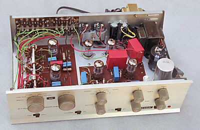 Right:
The modified PAS preamplifier, (re)built in 1996.
Right:
The modified PAS preamplifier, (re)built in 1996.
"A New Dynaco PAS Upgrade," Glass Audio, Vol. 6, No. 4, 1994,
addressed several of the PAS problems. The chassis and power supply were
modified and cathode followers were added to the phono preamplifier
and line amplifier. One version of the line amplifier was designed with
switchable tone controls. Another-- the purist version-- was designed without
them.
The power supply modifications consisted of
replacing the filament supply rectifier and filter capacitor with modern
compact versions to make room for two additional tube sockets behind the
line amplifier circuit board, replacing the 12X4 rectifier with silicon
diodes (fast recovery recommended), increasing the B+ supply capacitance,
and decreasing the resistors in the B+ supply to compensate for the additional
current drawn by the cathode followers. A separate filament transformer
was mounted on the back of the PAS chassis so the current drawn by the
two additional tubes didn't overheat the power transformer. The present
modification uses the same chassis alterations and nearly the same power
supply. The new power supply schematic is shown below. (I'll fix it up
with PSpice one of these days.)
Modified PAS suggested power supply
 I'd
make one significant change to the power supply circuit (above). I'd get
rid of RS1, the 1 ohm 2W resistor used to drop the filament supply voltage
to the appropriate level (around 25V for this arrangement, where pairs
of tubes are wired in series), and I'd replace it with an LM317T voltage
regulator circuit between the rectifiers (FR303) and the tube filaments.
I would do so for reliability-- it would make the voltage across the tube
filaments independent of the current. It wouldn't have much effect on sound
quality. The circuit would be similar to 12.5V supply in The
Emperor's New Amplifier, with CH3 and CH4 omitted. The diagram on the
right is lifted from the PDF
data sheet for the National
Semiconductor LM317. C1 is needed only if the device is more than 6
inches from filter capacitors. C2 can be omitted since this is not a signal
circuit. The output voltage is
I'd
make one significant change to the power supply circuit (above). I'd get
rid of RS1, the 1 ohm 2W resistor used to drop the filament supply voltage
to the appropriate level (around 25V for this arrangement, where pairs
of tubes are wired in series), and I'd replace it with an LM317T voltage
regulator circuit between the rectifiers (FR303) and the tube filaments.
I would do so for reliability-- it would make the voltage across the tube
filaments independent of the current. It wouldn't have much effect on sound
quality. The circuit would be similar to 12.5V supply in The
Emperor's New Amplifier, with CH3 and CH4 omitted. The diagram on the
right is lifted from the PDF
data sheet for the National
Semiconductor LM317. C1 is needed only if the device is more than 6
inches from filter capacitors. C2 can be omitted since this is not a signal
circuit. The output voltage is
VOUT = 1.25(1+R2/R1) + IADJ(R2)
I leave it to the reader to calculate R2. The filaments of a 12AX7, series
wired, draw 0.15 A. The six tubes in this series-parallel arrangements
draw 0.45 A, well under the LM317T's 1.5 A capacity. (Other versions of
the LM117/317 have lower power handling capacity.) The LM317T is inexpensive
and widely available (yes, you can get it at the Shack).
The '94 mod solved several problems but left others untouched. Distortion
in the overloaded line stage was greatly reduced by the addition of the
cathode follower and very low impedance loads could be driven, but increased
open-loop gain reduced the stability of both the phono preamplifier and
line amplifier. The phono preamplifier response was still sensitive
to the individual tube. The low frequency line amplifier resonance was
still present. All of these problems have been fixed in the new design.
To Part 2: New preamplifier
designs
References
-
Norman L. Koren, "Improved Vacuum-Tube
Models for SPICE Simulations," Glass Audio, Vol. 8, No. 5, 1996, p. 18.
-
Paul W. Tuinenga, "SPICE, A
Guide to Circuit Simulation & Analysis using PSpice," Prentice-Hall,
1992 or 1995.
-
Scott Reynolds, "Vacuum-tube
models for PSPICE simulations," Glass Audio, vol. 5, no. 4, 4/93 p. 17.
-
W. Marshall Leach, Jr., "SPICE
models for vacuum-tube amplifiers," J. Audio Eng. Soc. Vol 43, No. 3, March
1995, p. 117.
-
Norman Koren, "A new Dynaco
PAS upgrade," Glass Audio, vol. 6 no. 2, 2/94, p. 10.
-
Paul Miller, "Resonances and
Repercussions," Hi Fi News & Record Review, June 1989, p. 35.
-
John Bicht interview, "Rethinking
Preconceptions," Stereophile, vol. 19, no. 6, June 1996, p. 160.
-
Rick Miller, "Measured RFI Differences
Between Rectifier Diodes...," The Audio Amateur, 1/94, p. 26..
-
Ronald M. Bauman, "Feedforward
Error Cancellation," The Audio Amateur, 2/96, p. 10.
-
Christopher Paul, "The greening
of the cascade feedback pair," Glass Audio, vol. 7, no. 5, 5/95, p. 20.
-
Tom Mitchell, "The Audio Designer's
Tube Register Volume 1," Media Concepts, Norwalk, CA.
-
Dimitri Danyuk and George Pilko,
"Error Correction in Audio Amplifiers," Journal of the Audio Engineering
Society, Vol. 44, No. 9, Sept. 1996, p. 721.
-
Jimmie D. Felps, "One extra
resistor fights IC op-amp oscillations," EDN, July 3, 1997, p. 129.
About the author
Norman Koren, a native of Rochester, NY,
received a BA in physics from Brown University in 1965 and an MA in physics
from Wayne State University in 1969. His destiny as a high-tech nomad has
taken him to Boston, Philadelphia, Silicon Valley, San Diego, and most
recently to Colorado, where he worked in research and development of digital
magnetic recording channels through 2001.
To Part 2: New preamplifier
designs
Norman Koren Vacuum tube audio page
| Photography page
Feedback and Fidelity
| Improved vacuum tube models for SPICE
simulations
.
This page
was created December 8, 2003 |
Images
and text copyright © 2001-2003 by Norman
Koren. Norman Koren lives in Boulder, Colorado, where he worked
in developing magnetic recording technology for high capacity data storage
systems through 2001. He has been involved with photography since 1964.
Designing vacuum tube audio amplifiers was his passion between about 1990
to 1998. |
 |